At 1 GHz, a 10 kΩ resistor can measure only 1.6 kΩ1 GHz では、10 kΩ の抵抗器が 1.6 kΩ になることがある
I started this series after this post.
この投稿がきっかけで、このシリーズを始めました。
Seriesシリーズ · Part 1 of 81 / 8
All parts ↓すべての回 ↓Why a resistor isn’t just a resistor抵抗器は、ただの抵抗ではない
Goal: ゴール:Learn why a resistor stops being just a resistor at high frequency.高い周波数で、抵抗器がただの抵抗でなくなる理由を知る。
In one lineひとことで
A part works like its circuit symbol only at low frequency.
A resistor is often the first part you meet in electronics. It makes current harder to flow and turns energy into heat. It’s a very simple part.
But at high frequency, things change. Measure a 10 kΩ resistor at 1 GHz, and you may see only about 1.6 kΩ.
The cause is something like a tiny inductor (L) and a tiny capacitor (C) hidden inside the resistor. In this example, they are 1 nH of inductance (a tendency to resist changes in current) and 0.1 pF of capacitance (the ability to store charge).
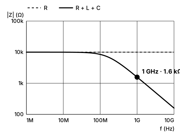
In the chart, the dashed line (R) is an ideal resistor. It stays at 10 kΩ at every frequency. The solid line (R + L + C) is a more realistic resistor with that L and C. Its measured value starts to drop around 100 MHz and reaches about 1.6 kΩ at 1 GHz.
1 GHz isn’t an exotic number. Wi-Fi uses radio waves at 2.4 GHz and 5 GHz. Phones talk over GHz radio waves too.
Those signals travel through circuits inside the device, and the resistors there run into the same thing. That’s why Vishay, a parts maker, sells special resistors that stay almost pure resistors up to 40 GHz. Ordinary ones can’t.
It isn’t only resistors. Above a certain frequency, a capacitor works like an inductor.
This is the interesting part. A resistor’s circuit symbol shows only resistance. That’s enough only while signals change slowly. When signals change fast, the magnetic and electric fields around wires start to matter. Then parts show sides their symbols don’t. Knowing one resistor well shows you how electricity really works.
This series goes step by step, starting from voltage and current. You don’t need any background.
References参考資料
In one lineひとことで
部品が回路記号どおりに働くのは、低い周波数のときだけです。
抵抗器は、電子工作で最初に出会う部品です。電流を流れにくくして、エネルギーを熱に変えます。とても単純な部品です。
ところが、高い周波数では話が変わります。10 kΩ の抵抗器を 1 GHz で測ると、約 1.6 kΩ しかないことがあります。
原因は、抵抗器の中にかくれている、小さなコイル(L)とコンデンサ(C)のような性質です。この例では、1 nH のインダクタンス(電流の変化に逆らう性質)と、0.1 pF のキャパシタンス(電気をためる性質)があるとしています。
グラフの点線(R)は、理想の抵抗器です。周波数が変わっても 10 kΩ のままです。実線(R + L + C)は、この L と C を持った、実際に近い抵抗器です。100 MHz あたりから測った値が下がりはじめ、1 GHz では約 1.6 kΩ になります。
1 GHz は、特別な世界の数字ではありません。Wi-Fi は 2.4 GHz や 5 GHz の電波を使います。スマートフォンも GHz の電波で通信しています。
こうした電波の信号は、機器の中の回路を通ります。その回路の抵抗器にも、同じことが起きます。だから部品メーカーの Vishay は、40 GHz まで抵抗としてほぼそのまま働く、特別な抵抗器を売っています。ふつうの抵抗器では、そうはいかないからです。
抵抗器だけではありません。コンデンサも、ある周波数をこえるとコイルのように働きます。
ここが面白いところです。回路図にある抵抗器の記号は、「抵抗」の働きしか表していません。それで足りるのは、信号がゆっくり変わるときだけです。信号が速く変わると、導線のまわりの磁場や電場が無視できなくなります。すると部品は、記号にはない性質を見せはじめます。抵抗器ひとつをよく知ると、電気の本当の動きが見えてきます。
このシリーズでは、電圧と電流の基本から一歩ずつ進みます。予備知識はいりません。